The quality of your mesh is critical to obtaining accurate results from your analyses. You’ll often hear the term “convergence analysis” tossed around in the Finite Element Analysis (FEA) world. This simply means we want to make sure the mesh in critical areas is fine enough so the results we get from the analysis are independent of the mesh size.
One such place we often see high stress is in corner areas. Fillets are generally added in these locations to help distribute stress better. When we are analyzing these filleted areas, it’s important we have a mesh fine enough to capture that distribution of stress.
In order to make our problem run most efficiently, we don’t want to refine the mesh over the entire geometry just to get the mesh in the filleted areas fine enough. To get around this problem, more often than not we will add mesh controls on these fillets in order to refine the mesh just in the localized area.
A More Efficient Way to Add Mesh Controls to Every Fillet
Did you know you’re just creating extra work for yourself by adding mesh controls to every single fillet? SOLIDWORKS Simulation has multiple meshing algorithms that can be used; however, in most cases, we recommend using the curvature-based mesher.
The curvature-based mesher has multiple settings most people just gloss over. Even if they know technically what each field does, they often don’t think through how they can use those settings to their advantage.
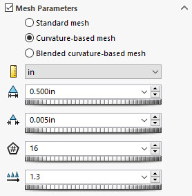
These are the settings:
- Maximum Element Size
- Minimum Element Size
- Min Number of Element in a Circle
- Element Size Growth Ratio
Maximum and Minimum Element Size
The Max and Min Element Size is pretty straight forward. It tells the mesher how much freedom it has to fluctuate the element sizes to adequately mesh the geometry.
Min Number of Element in a Circle
The Min Number of Element in a Circle is an interesting setting that can be powerful when used correctly. This field forces any circular feature to have a minimum of the specified number elements around it. This includes a true circular feature such as a hole, but it also applies to arcs as well; fillets would fall into this category. With this in mind, this field can be leveraged in order to have better control of the mesh in these high-stress areas.
Element Size Growth Ratio
Along with the Min Number of Elements in a Circle, the Element Size Growth Ratio can be used to give your mesh a good transition away from high-stress areas.
The key to making this work well is by ensuring there is enough of an interval between your max and min element size. This allows the mesher to meet the requirement of the min number of elements in a circle. This field can be set as large as possible, but if the elements aren’t allowed to get small enough to achieve that, then it won’t do anything. A good way to determine the size of small features in your model is to use Geometry Analysis.
General Rule of Thumb for Fillets
A general rule of thumb for fillets is to have 3-4 elements through the radius. This means the minimum element size should be the smallest fillet size divided by however many elements you want over the filleted face.
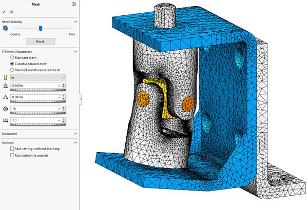
By just inputting a few numbers into the global mesh settings, I was able to adequately mesh all the filleted regions of this model without using a signal mesh control. Now that’s what I call efficiency!
Share
Meet the Author
view all posts by GSC
SOLIDWORKS Webinars & Power Hours
