We’re in Part 3 of our SOLIDWORKS Flow Simulation series! So far we’ve covered the basics and the stages and we took a closer look at a basic mesh. Now we’re going to take a closer look at an initial mesh.
The initial mesh of a Flow Simulation is the first mesh used for performing actual calculations. The software starts with the basic mesh, then refines area with certain geometrical features based on the different settings in the software. This post will be a discussion of those settings.
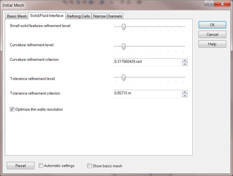
Before we discuss the actual settings, let’s talk about what all the level settings are since we see it multiple times in Small solid features refinement level, Curvature refinement level, and Tolerance refinement level.
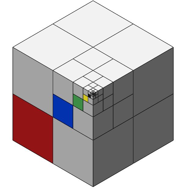
The refinement level is the maximum amount of times a cube that represents a cell can be split. Each cube splitting into 8 equal cubes represents one level. The image below shows multiple refinement levels. If all the cells combine to make one starting cell, then the following is a table to put the different refinement levels in the image in perspective:
- Level 1: Red
- Level 2: Blue
- Level 3: Green
- Level 4: Yellow
- Level 5: Black
- Level 6: White
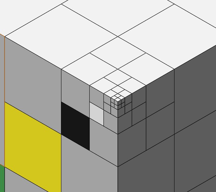
- Level 7 and Level 8: Uncolored because they are too small to make out. See the second image for zoomed in view.
You can imagine how many cells would be created if every cell was refined eight times. The actual amount would be 8^8 or 16,777,216. That means that a single cell that would normally take about 10 kB of RAM to store would now produce about 16GB of RAM needed if all cells created by refinements were continually refined up to the max as well. And, that’s just from one cell out of the basic mesh! There can be thousands or millions in the basic mesh! This is why the settings exist, so the software can sort out what needs refinement and what doesn’t – otherwise you would never finish an analysis in any reasonable timeframe.
Two things work for us here. First, it’s unlikely all cells from each refinement will ever continue to be refined, typically making the mesh much less resource intensive then 8^8 cells from one cell would indicate. Second, solution adaptive meshing only refines cells that need it as the solution progresses keeps things efficient. We’ll be talking more about that in a later post in this series. For now, we’ll move on to settings of the initial mesh.
Small solid features refinement level: Allows refinement around features in which one or more dimensions is small compared to other features around it. Think of features that are thin, short, etc.
Curvature refinement level: Looks at surfaces with too much curvature and refines them as many times as allowed by what you have set This is done to minimize errors from bad discretization of a curved surface by a rectangular/cubic cell.
Tolerance refinement level: Used to make sure the deviation of the discretization from the actual surface geometry is not so large to cause issues. If you think of a quarter circle in a single cell, its solid representation is actually going to be a triangle made by the edges of the cell and a line connecting the two points the quarter circle intersects with the cell edges. If this discretization error is large, then splitting cells makes it more accurate.
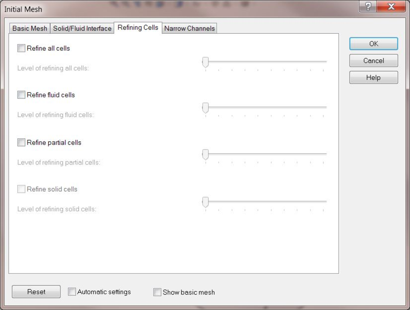
In the refining cells tab, the options are simple. Tell the software how many times you want it to split each cell type before starting its run.
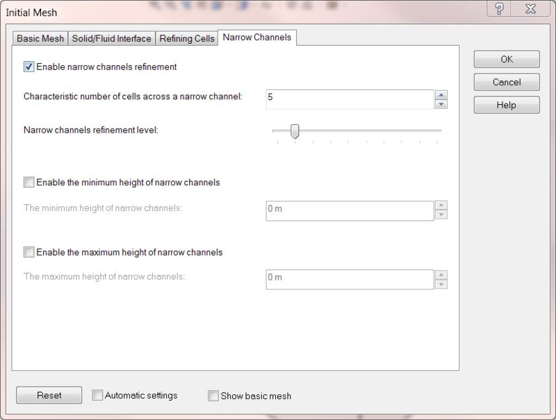
The Narrow Channels tab deals with areas where flow conditions occur in small gaps. It allows an input of the minimum number of cells you desire, as well as a refinement level of how many times you will allow the software to split the cells in an attempt to achieve that. The process stops when either setting is hit.
Turning on the bottom two options for minimum and maximum height of narrow channels limits what constitutes a narrow channel. Otherwise, the entire global domain, or local domain if you are using the local initial mesh settings, is used.
That is the basic settings for the initial mesh. In the next portion of this post, I will be discussing solution adaptive mesh settings. I hope you’re interested!
Share
Meet the Author
view all posts by GSC
SOLIDWORKS Webinars & Power Hours
