Saying there is a lot to know about meshing as it relates to Computational Fluid Dynamics (CFD) is a massive understatement. Fortunately, for the most part, SOLIDWORKS Flow Simulation automates much of this for you. But, what if that’s not enough?
Automatic meshing is done to ensure adequacy for a less-skilled user. What if you want more accuracy? What if you want more time efficiency from your solution? Well, that’s when you need to become an advanced user and start to use manual settings.
As I mentioned, meshing in CFD is a large topic. This post will be the first of a multi-post series addressing the topic. My goal in this post is to get you to understand the stages of meshing, then in future posts we’ll talk about settings and how those settings affect the mesh at different stages.
The stages of meshing in CFD are:
- Basic Mesh
- Initial Mesh
- Solution-Adaptive Mesh
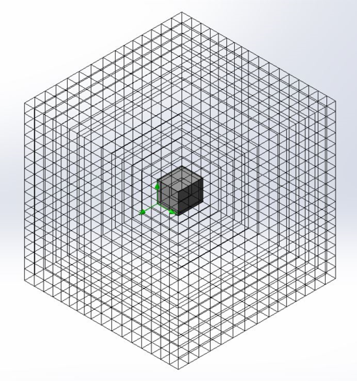
Basic Mesh
Basic Mesh is the first mesh made. In most cases, it breaks the computational domain into cells that are all equally sized, ignoring model geometry. If using manual settings, typically the number of cells in the x-, y- and z-directions are input by the user to determine the total number of starting cells of the 3D grid.
Initial Mesh
The initial mesh takes software defaults or user input settings related to model geometry and refines the basic mesh around the model geometry. Areas of curvature, thin walls, and narrow channels all play into how much the cells get refined.
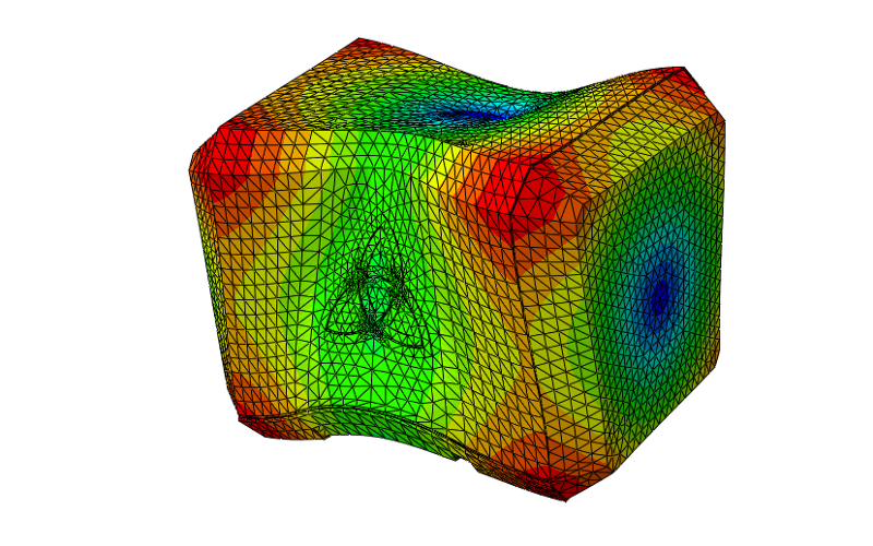
Solution-Adaptive Mesh
This is when the software refines the mesh based on the flow characteristics taking place in order to accurately capture the flow. Since we don’t know flow characteristics until enough iterations are solved for the flow to have developed, this takes place during the calculation stage.
Each stage has its own settings. In the future blog posts of this series, I will discuss the settings for these different meshing stages. Stay tuned!
How to Use Meshing in SOLIDWORKS Flow Simulation – Part 2
In Part 2 – we take a closer look at the basic mesh. It is the first stage of a CFD problem. It only sets its size based on the computational domain and ignores the model shape. To set this up, there are multiple settings related to it. Join us for Part 2.
Share
Meet the Author
view all posts by GSC
SOLIDWORKS Webinars & Power Hours
