Solidworks Simulation
Table of Contents
Exploring SolidWorks Simulation Essentials
In today’s fast-paced engineering world, virtual testing tools like solidworks simulation save countless hours by predicting product behavior before physical builds. We at GSC 3D see this as a game-changer for manufacturers seeking efficiency without compromising reliability.
SolidWorks Simulation serves as an embedded add-in within SOLIDWORKS CAD software, enabling finite element analysis (FEA) for structural, thermal, and flow simulations. It integrates seamlessly with your 3D models, allowing engineers to test designs under real-world conditions such as stress on an automotive bracket or heat distribution in aerospace components. Key applications span manufacturing sectors like automotive and aerospace, where solidworks fea validates durability, while solidworks flow simulation acts like a digital wind tunnel for fluid dynamics using CFD tools within CAD. Available in packages from standard to premium, it supports everything from basic static studies to advanced nonlinear analyses.
This guide walks you through activation, core FEA setups, and flow simulation techniques, building from fundamentals to expert workflows. As an authorized reseller, we at GSC 3D offer tailored training and integration services to optimize your simulation processes nationwide.
Preparation for SolidWorks Simulation
Before embarking on solidworks simulation projects, we recommend verifying essential prerequisites to avoid disruptions in your structural analysis tools in SOLIDWORKS or fluid dynamics modules. This preparation ensures smooth integration of solidworks fea capabilities for stress testing and solidworks flow simulation for thermal analyses.
Start with software and hardware requirements. SOLIDWORKS 2021 or later is the minimum version for robust simulation features, supporting advanced computations without compatibility issues. Hardware needs include a multi-core CPU for efficient processing, at least 16GB RAM to handle complex models, and a dedicated graphics card for visualization. These specs prevent performance bottlenecks during intensive simulations.
Next, check your solidworks license entitlements specifically for simulation add-ins. Access the SOLIDWORKS Help menu or license manager to confirm activation rights for modules like Simulation Professional or Premium. Without proper licensing, features for solidworks fea or flow simulations remain inaccessible, leading to workflow delays.
To activate the Simulation add-in, navigate to Tools > Add-Ins in the SOLIDWORKS interface, as detailed in official documentation. Select the Simulation option and enable it at startup for seamless access. Ensure your model is compatible–parametric, feature-based assemblies work best–and consider integrating with SOLIDWORKS PDM for organized data management across teams.
We at GSC 3D offer expert license troubleshooting and support to streamline your setup. Contact us for personalized guidance on entitlements and activations.
Preparation Checklist:
- Verify SOLIDWORKS version (2021+).
- Confirm hardware meets minimum specs.
- Check simulation add-in licenses.
- Activate via Tools > Add-Ins.
- Prepare compatible models and PDM integration.
Activating the Simulation Add-In
Enabling the solidworks simulation add-in is essential for accessing advanced tools like solidworks fea and solidworks flow simulation within your SOLIDWORKS environment. As a trusted SOLIDWORKS reseller, we guide you through this straightforward process to unlock virtual testing capabilities for structural analysis and fluid dynamics.
- Launch SOLIDWORKS and navigate to the Tools menu, then select Add-Ins.
- In the Add-Ins dialog, locate SOLIDWORKS Simulation in the list and check the box to enable it. For convenience, also select the Start-up option to load it automatically in future sessions.
- Click OK to apply changes. The Simulation toolbar should now appear, providing immediate access to features like the add-in for structural testing and flow analysis activation.
- If the add-in does not load, verify your license through the SOLIDWORKS administration tools and restart the application.
Activating this add-in matters because it empowers engineers to perform accurate simulations directly in the design phase, reducing physical prototyping needs and enhancing product reliability.
For optimal use, ensure your SOLIDWORKS license includes simulation packages; contact us for license troubleshooting if issues arise.
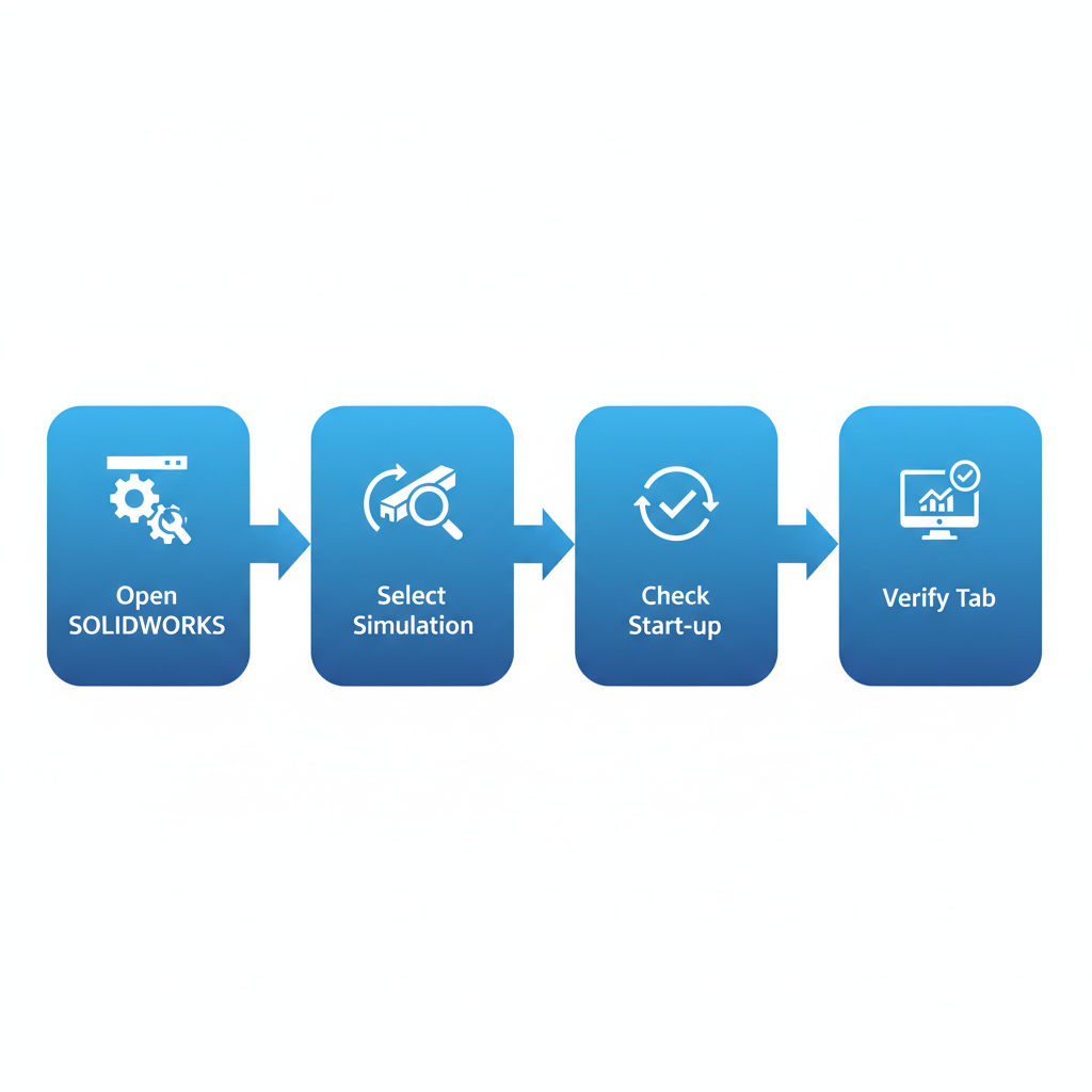
Steps to activate the SOLIDWORKS Simulation add-in
Understanding Simulation Packages
We understand that selecting the right solidworks simulation package is crucial for effective engineering analysis. SOLIDWORKS offers tiered options to match various needs in finite element analysis and beyond. The Premium package focuses on linear static and thermal studies, ideal for basic structural evaluations using solidworks fea tools. The Professional edition builds on this with nonlinear analysis and fatigue assessments, enabling deeper investigations into material behaviors under complex loads.
The full Simulation package extends capabilities further, incorporating solidworks flow simulation for fluid dynamics alongside advanced structural modules. These distinctions allow users to choose package options for analysis that align with project demands, such as distinguishing structural vs fluid tools.
Upgrade paths are straightforward, starting from Premium to Professional or full Simulation as requirements evolve. At GSC 3D, as a trusted SOLIDWORKS reseller, we manage licensing to ensure seamless transitions.
Understanding these packages matters because they directly impact the depth of your analysis, from simple stress checks to comprehensive multiphysics simulations that inform design decisions and reduce prototyping costs.
For tailored advice, we recommend consulting resellers like GSC 3D to evaluate your solidworks fea needs. Our solidworks training programs can help teams master these tools efficiently, ensuring optimal use of your license investment.
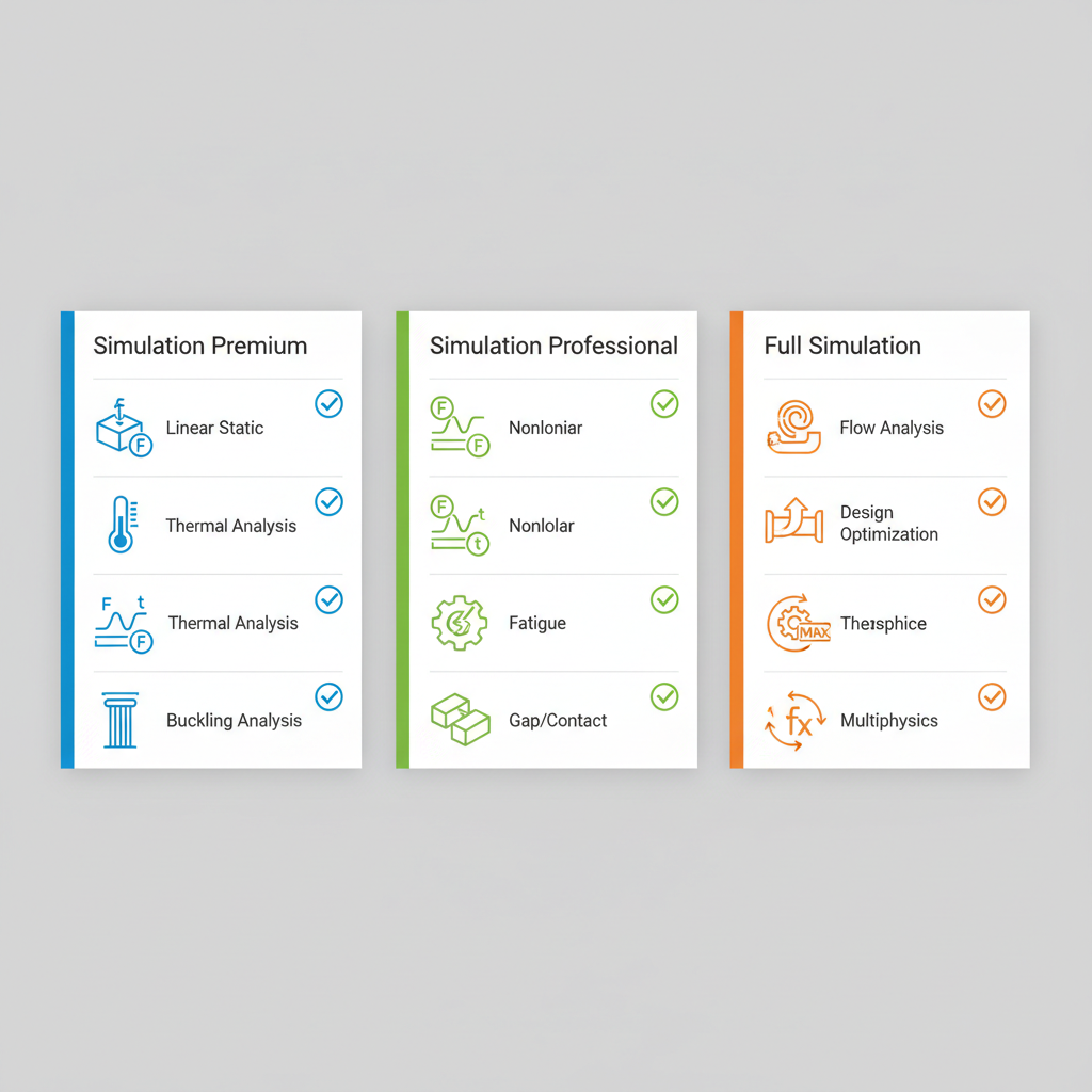
Comparison of SOLIDWORKS Simulation packages features.
Setting Up Your First Simulation Study
As a trusted SOLIDWORKS reseller, we at GSC 3D guide beginners through the essentials of solidworks simulation to perform reliable analyses. Starting your first study in SolidWorks Simulation lays the foundation for effective solidworks fea, whether exploring static loads or thermal effects.
- Open your model in SOLIDWORKS and navigate to the Simulation tab in the CommandManager.
- Click New Study and select the type, such as Static for structural analysis or Thermal for heat transfer–avoiding solidworks flow simulation for now if focusing on basics.
- Choose appropriate units (e.g., SI or IPS) from the Options dialog.
- Define study properties like mesh type and solver settings in the Study Properties dialog.
- Save your setup via File > Save As, naming it clearly for study creation for testing.
This beginner analysis setup ensures simulations yield accurate, actionable insights without errors from mismatched parameters.
Tip: Save frequently during configuration to safeguard your progress, especially as you advance to meshing.
Defining Materials and Meshes
In SolidWorks Simulation, we begin defining materials and meshes after setting up the study to ensure reliable finite element analysis (FEA) outcomes. This foundational step involves importing and applying materials from the built-in library, where we select properties like Young’s modulus and Poisson’s ratio for accuracy. For instance, we might assign steel [AISI 304] to a component, then modify density or thermal conductivity if needed for specific SolidWorks FEA scenarios.
Next, we generate the mesh using standard or curvature-based options to discretize the geometry. Standard meshes suit simple parts, while curvature-based ones capture finer details in curved surfaces. Refining the mesh iteratively improves result precision, especially for complex SolidWorks flow simulation or fatigue analysis. Material assignment in FEA directly impacts stress distributions, while meshing for flow studies affects velocity predictions; inaccuracies here can invalidate entire simulations. We recommend starting with a coarse mesh to quickly assess convergence before refining to target element sizes around 1-5 mm for most tolerances, balancing computational efficiency and validity.
Applying Loads and Fixtures for FEA
After meshing your model, the next critical step in our solidworks simulation workflow is defining boundary conditions to ensure accurate solidworks fea results. We guide clients through selecting faces or edges for fixtures, such as fixed geometry to prevent all movement or roller sliders that allow motion in one direction. Forces can be applied as distributed loads on surfaces, while pressures simulate fluid interactions similar to those in solidworks flow simulation. Gravity and centrifugal forces are also essential for assemblies, often using connectors to link components realistically.
Proper load setup for simulations mirrors real-world operating conditions, enabling precise predictions of stress, deformation, and failure points in manufacturing parts. This boundary conditions in structural analysis approach validates designs before production, reducing costly iterations and enhancing safety.
Always verify units for consistency, double-check fixture orientations to avoid unrealistic constraints, and preview results iteratively. These practices lead seamlessly into running the analysis for actionable insights.
Running and Interpreting FEA Results
Once we have defined the loads and boundary conditions in our SolidWorks Simulation study, executing the analysis is straightforward. We often leverage simulia solvers to run the study. We initiate the run by selecting the study type and clicking the solve button, allowing the software to compute the finite element model. This process validates designs through solidworks fea, providing critical insights into structural integrity.
To interpret results, we view stress and displacement plots, which visualize how the model deforms under applied forces. Using probe tools, we measure specific values at points of interest, such as maximum von Mises stress or total deformation. We then assess safety factors to ensure the design exceeds failure thresholds; for instance, predicting part failure in high-load scenarios like automotive components helps prevent real-world issues.
These actionable insights inform design decisions, optimizing performance and reducing risks. Interpreting results accurately guides iterations, ensuring compliance and efficiency.
For best practices, we validate FEA outcomes with physical tests to confirm accuracy. Export detailed reports to document findings, facilitating team reviews. This approach seamlessly transitions to exploring solidworks flow simulation for fluid dynamics analysis.
Introduction to Flow Simulation
At GSC 3D, we leverage SOLIDWORKS simulation tools to enhance manufacturing designs through advanced analysis. SOLIDWORKS Flow Simulation extends traditional SOLIDWORKS FEA by incorporating computational fluid dynamics (CFD) for evaluating fluid flow and thermal fluid analysis in product development.
To begin, enable the Flow Simulation add-in from the Tools menu in SOLIDWORKS. Create a new flow study by selecting internal or external analysis type, which simulates enclosed or open environments. Define project goals such as average velocity, static pressure, or temperature at specific points. Then, apply boundary conditions like inlet velocity, outlet pressure, or heat sources to model real-world scenarios accurately. These steps, typically taking under 70 words to outline here, form the foundation for reliable simulations.
This capability optimizes designs by predicting performance issues early, such as airflow in heat sinks for electronics cooling, reducing prototyping costs and iterations in manufacturing applications.
For best results, monitor mesh convergence during solving to ensure accuracy, and validate results against empirical data. We recommend starting with simple models to build confidence in interpreting flow patterns and thermal gradients.
Troubleshooting Simulation Issues
When working with solidworks simulation, users often encounter challenges that disrupt their workflow, such as convergence failures in studies, mesh generation errors, and license activation problems. These issues can arise during finite element analysis (FEA) tasks or computational fluid dynamics (CFD) setups, impacting efficiency in engineering projects. At GSC 3D, we recognize these pain points and provide guidance to help resolve them swiftly, ensuring smoother integration of solidworks fea and solidworks flow simulation into your design processes.
To address common problems, start with a diagnostic checklist. For non-converging studies, refine the mesh density in critical areas and verify boundary conditions and loads, as recommended in SOLIDWORKS documentation on performing static analysis. Meshing failures often stem from complex geometry; simplify the model by suppressing small features or using defeature tools before remeshing. Add-in crashes may require checking compatibility with your SOLIDWORKS version–reinstall the simulation add-in via the Tools menu, following official activation procedures. License errors typically involve activation keys or network issues; verify your subscription status through the license manager and restart the software.
For large models, optimize by dividing the assembly into subassemblies or using remote loads to reduce computational demands, particularly in debugging FEA runs or troubleshooting CFD setups. Prevention tips include regular software updates, maintaining clean geometry, and running preliminary mesh checks before full simulations to catch issues early.
If problems persist, our team at GSC 3D offers expert simulation and FEA support as a trusted SOLIDWORKS reseller. Contact us for personalized assistance to get your projects back on track, or explore our solidworks courses for hands-on training.
Mastering SolidWorks Simulation for Engineering
Mastering solidworks simulation empowers engineers to validate designs with precision, from initial setup to detailed analysis. We have explored activating the tool, selecting appropriate packages, and guiding you through solidworks fea workflows–from defining loads and constraints to interpreting stress results. An introduction to solidworks flow simulation highlighted fluid dynamics applications, while troubleshooting tips addressed common pitfalls like mesh quality and convergence issues.
These processes accelerate design iterations, reducing time to market and enhancing product reliability through advanced FEA techniques and integrated flow tools. By simulating real-world scenarios early, manufacturers minimize physical prototypes and costly errors.
To build on this foundation, we invite you to explore advanced training options tailored for your team.
As a trusted SOLIDWORKS reseller, GSC 3D offers SOLIDWORKS CAD Manager’s Bootcamp and comprehensive simulation support to integrate these capabilities seamlessly into your workflows.
Resources


Companies that trust GSC


")


")