As an engineer, you are on a never-ending quest to efficiently produce meaningful designs to generate amazing and profitable results. On your quest, you must be resourceful and you sometimes must use new methods to get where you’re going! There are also rules along the way to help you get where you’re going with much less hassle and strain…never starting land wars in Asia comes to mind.
An important tool for your quest as a SOLIDWORKS Electrical user is the 2D Cabinet layout feature. It’s no surprise the 2D cabinet layout tool in SOLIDWORKS Electrical is quite proficient at laying out your cabinet enclosures and is filled with ducts, rails, and all of your design components. But, recent versions of SOLIDWORKS Electrical have made the feature easier to use and also much more versatile. So much so, the “2D Cabinet” name of the feature can be a bit…misleading. Consider that we’ve helped customers use the feature for it’s namesake, but also top level assembly layouts where key components are labeled (sensors with their IO addresses, Motors, switches, etc), or harness layouts can be efficiently represented using this drawing type as well!
First, the layout of your design parts can drive the wire cabling order based on their relative position. I don’t know about you, but the less time I spend manually ordering wires is a win! You can also get creative, using the space as a scalable area for laying out harnesses, placing tables, connection label information, or describing special relationships between design locations. But, before you dive into the possibilities, you need to know the background and settings that influence your results.
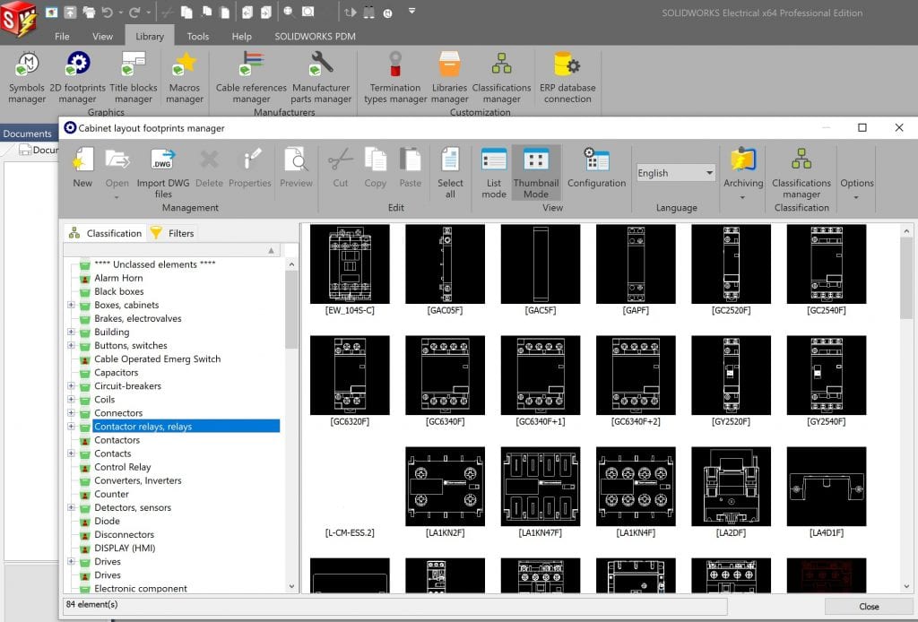
2D cabinet parts have their own Library section. You can use existing symbol geometry (copy, paste, and change symbol type) if you had a connection label or a line diagram symbol for which you can use the geometry.
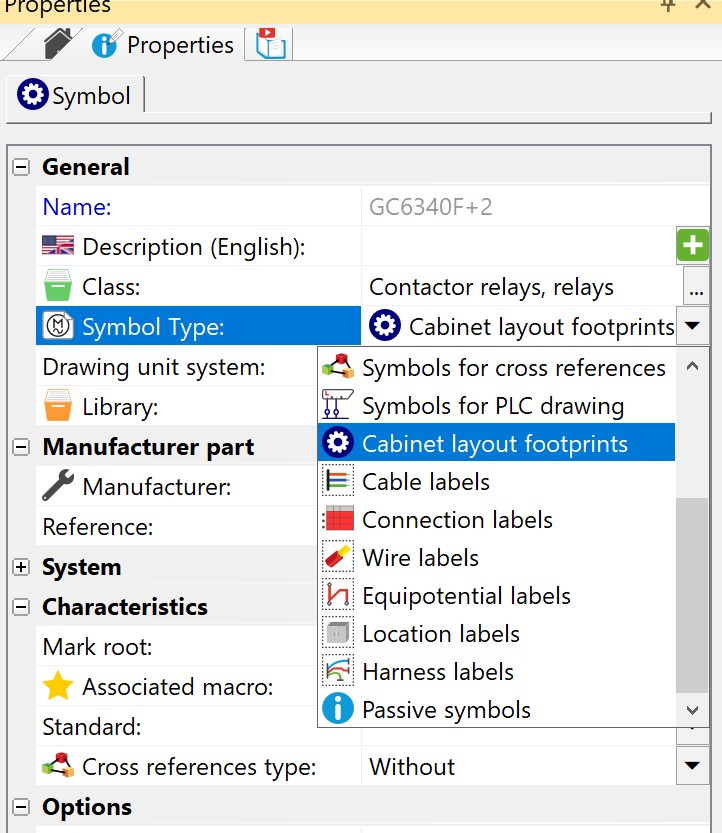
As soon as you change the symbol type, that 2D cabinet symbol will ONLY be available in the 2D cabinet library manager.
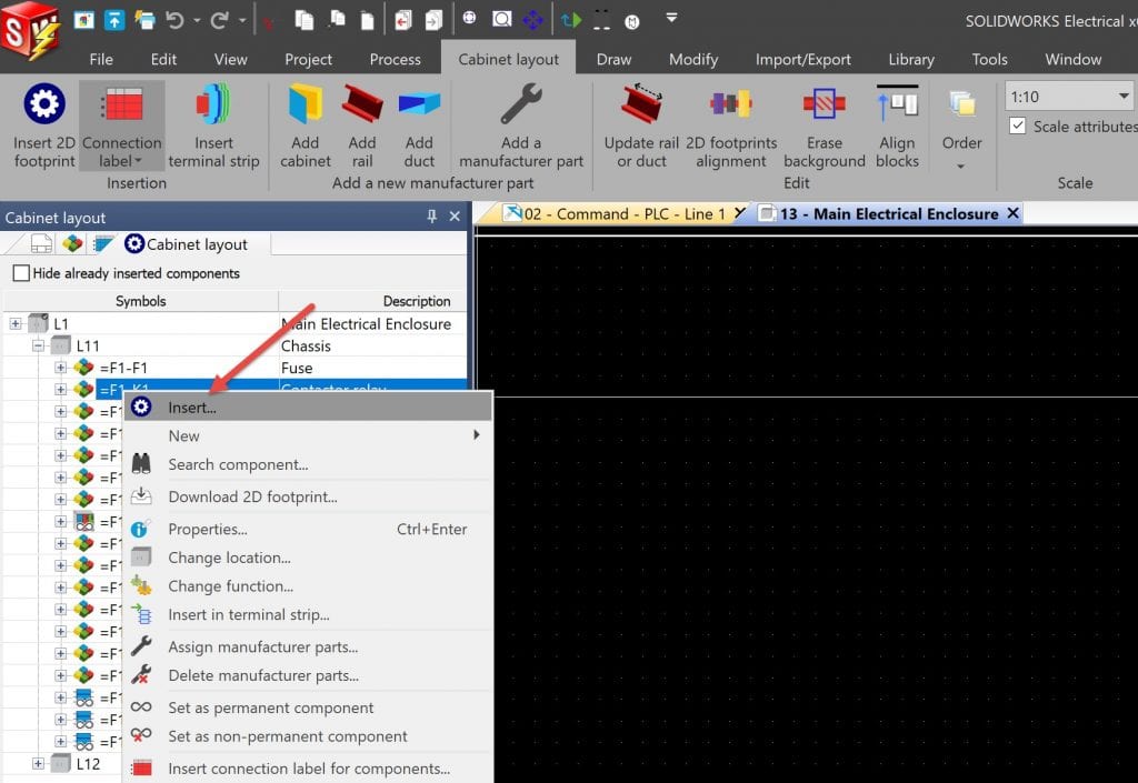
Inserting parts into 2D cabinet layout can be as simple as right-clicking on your part in the 2D cabinet layout feature and inserting.
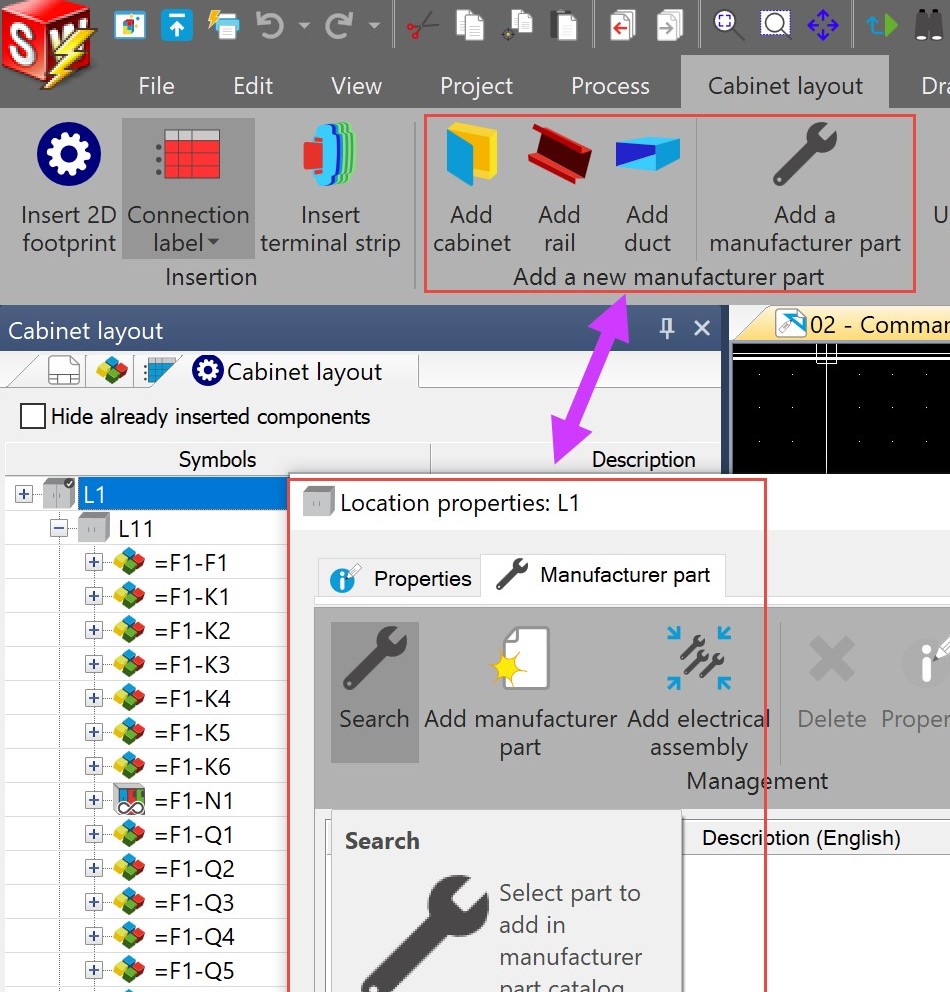
You can insert non-electrical parts directly to your location, such as enclosures, rails, ducts, and wire management accessories. Anything added with a part assigned in this way will show up on your final BOM reports as well!
On your quest, you may encounter “POUS,” or “parts of unusual size.” Conquering these buggers can seem intimidating at first as your parts can look scaled or warped. Both instances are by design, so fear not, the fix is not far away!
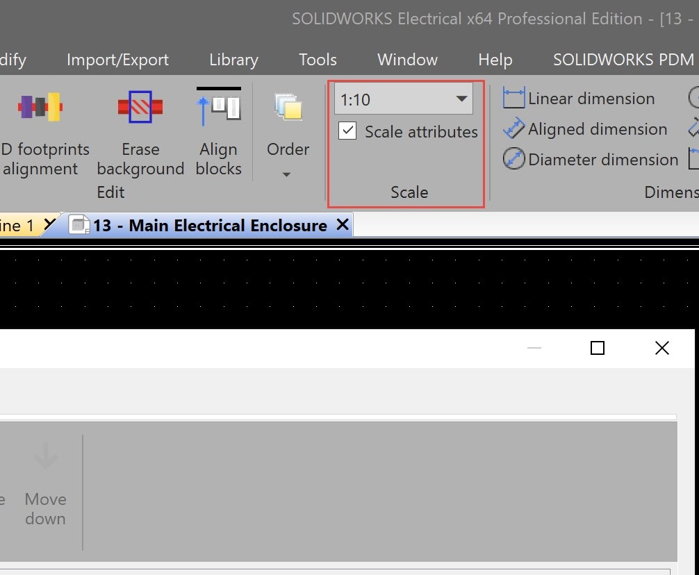
First, the layout will obey the scaling you’ve set for the 2D cabinet layout tool. You can change this setting on the fly, and the elements on the page will scale accordingly.
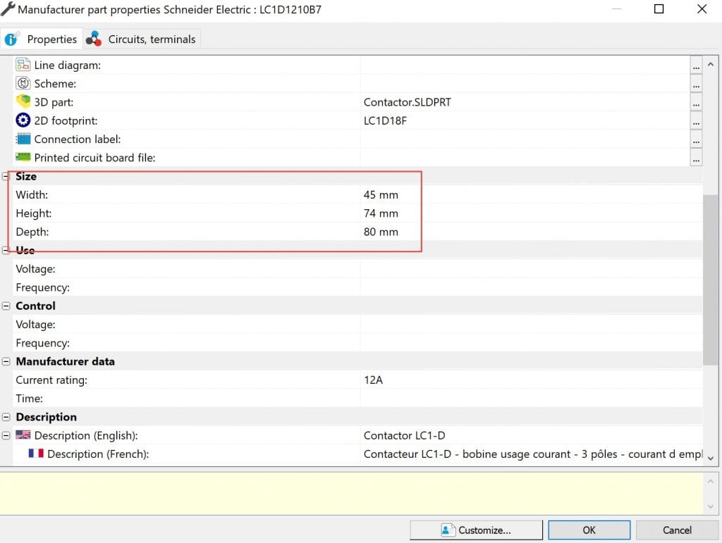
The second thing to check is if the 2D part dimensions are accurately defined as these dimensions will override the drawn symbol and scale it inappropriately. When you have made the changes to the dimensions, update the 2D symbol drawing. (As a side note, if these dimensions are correct, but no specific symbol has been applied to a particular part, inserting the 2D footprint can be represented by a simple box with the dimensions following the part size settings.)
Once your parts are properly proportioned and you’ve finished assembling your space, including your 2D electrical component footprints, you may also use the “Optimize Wire Cabling Order” command to reset your wire numbering order based on the proximity and location of the parts in your 2D layout drawing.
Not only will it re-order the wiring in your design, but it pays dividends in 3D as the routing algorithms will need fewer iterations to process the results. The larger the design, the more this benefit will have a positive impact.
Next time, with the background of the feature in hand, we will take a look at the specifics of filling up our library with the specific parts used on a day-to-day basis in your designs.
Share
Meet the Author
view all posts by Evan Stanek
SOLIDWORKS Webinars & Power Hours
