Before we dive into SOLIDWORKS Electrical Schematic and PLC addressing, our author has some context to share from his perspective as both teacher and student (that solidarity is important!) You’ll find the specifics of PLC addition and documentation in electrical projects, and automation of calculation and display of the terminal addressing in your PLC’s properties, further along in this blog. Enjoy!
As a teacher of all things SOLIDWORKS Electrical, I try to stay in touch with what it’s like to be a student…sitting in a class again, learning something strange and new for the first time. As a teacher during COVID times, we’ve smoothly converted to teaching everything online, and I’m proud to say we replicate 95% of the classroom experience. But, the biggest thing I miss is that deer-in-the-headlights look from the students. The look that says:

you said all about the things?” Image Credit: Chase Technology
Because with this look I then know, that I need to take another pass, try what I’m teaching from a different angle, and drum up another example. Lately I’ve been able to reconnect with that feeling as I picked up a few night classes myself! And as tough as it is pushing through that fog of learning, you know there’s great gains and mastery of content on the other side.
SOLIDWORKS Electrical PLC Addressing
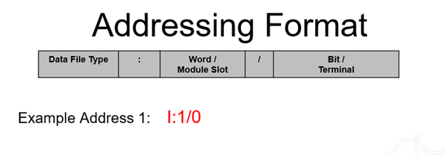
One such topic that I see needing the most clarity in SOLIDWORKS Electrical Schematic, is the PLC tools, especially addressing. Along with many other facets of PLC addition and documentation in your electrical projects, we can automate the calculation and display of the terminal addressing in your PLC’s properties. Take, for example, a PLC with addressing formatted like this:
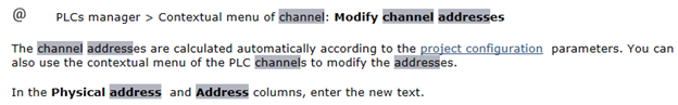
While we can paste or manually enter addressing into the PLC Input / Output (IO) grid to then display on our symbols or in reporting, it usually makes more sense to maximize SWE’s efficiencies and calculate our IO addresses. Now, here’s where the deer-in-the-headlights look happens. When new users attempt this, they’ll turn to the Help file and run into this (pictured):
Ummm, “Okayyy.” We’re back to the words of Homer Simpson.
A more helpful place to turn is the SOLIDWORKS Knowledge Base, which has a more fully developed explanation in S-062706. Let’s break this down: your PLC Channel Address is developed as follows:
- The Manufacturer Part (Reference) column for “Physical Address”
- The PLC’s per-use “Slot” variable from the Project component
- The Project’s formula for PLC Channel Addresses (found in your project configuration)
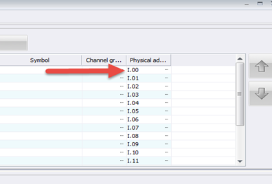
The first piece to the PLC puzzle is the manufacturer part. By going to your library and visiting a PLC classed part, your PLC IO circuits / terminals will have a special column that looks something like this:
The “Physical” address is part-level info, that then gets used to build the project address formula. Of most importance here is noting that everything before the period should reflect the MODULE TYPE, and you’ll want to ensure it reflects the syntax of your programming software. Everything after the period is the terminal’s ADDRESS BIT. These 2 positions relative to the period have a VARIABLE NAME in your project’s PLC formula section. They are known as “PLC_CHANNEL_TYPE” and “PLC_CHANNEL_ADDRESS.” Depending on your PLC’s software requirements, you can position those variables, adding critical static syntax in “QUOTATIONS” where needed.
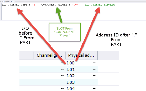
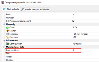
The middle variable shown in this formula is a PROJECT level variable that comes from the PLC Component itself. You can review and edit the “CARD POSITION” variable by going directly to the PLC component or visiting the Project>PLC Manager. The Card Position value fills in where the variable “COMPONENT_VALUE1” is positioned.
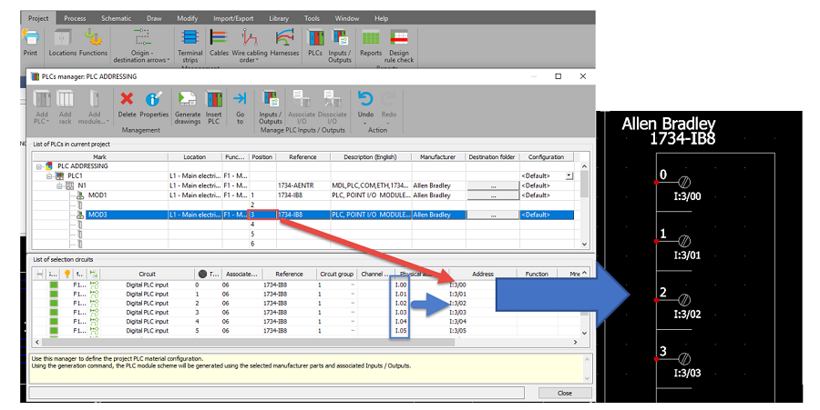
Here we see that selecting a module shows us the IO Physical Address along with the Card Position variable filling in to fully build the Address formula Automatically, which we can review in the PLC Manager and then display in our drawings when we “Insert PLC.”
A few helpful notes, after the image:
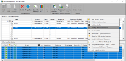
- You can modify your address formula if the addressing on a set of IO doesn’t fit the Project formula, just right click on selected circuits and choose “Modify channel address” to customize the exceptions on a case by case basis.
- In rare cases (Siemens addressing for instance where multiple slot addressing occurs on a single card) there is a 3rd variable that you can define from the part’s Physical Address definition, refer to the previously mention S-062706 to see if adding a slot index will aid in calculation.
- Remember, prior to setting up your IO to run the “Add New Input Output” command on the circuits.
- The Attribute to display the Circuit Channel Address in your PLC configuration is found in the Circuit>PLC section of the Attributes list, look for #C_CH_ADDR_0
PLC Addresses Video Tutorial
Check out this video to see it in action, and make the most of SWE’s PLC capabilities.
Contact Us
Did you like this tutorial? There’s more where this comes from. Find other blogs covering SOLIDWORKS Electrical by Evan or more on our YouTube Tech Tip videos.
Have a question? We’re always available to talk over the phone, for you to leave a message, or for you to submit a request – just contact us.
Share
Meet the Author
view all posts by Evan Stanek
SOLIDWORKS Webinars & Power Hours
