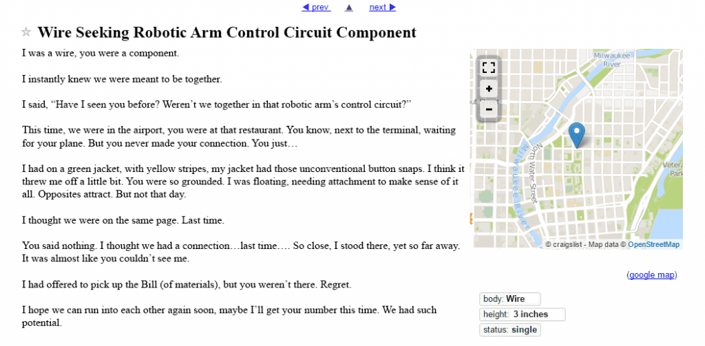
Have you ever read those “missed connection” posts on Craigslist? I learned of them from a radio morning show. The on-air personalities would read these tragic (yet hilarious) tales of lost love and near misses from people who swore they had missed their soulmate by mere meters, forever altering their destiny.
But, they always delivered the melodrama and were filled with regret. If only they had possessed the courage to make that connection, so their whole life could achieve its true meaning and purpose. Like I said, M-E-L-O-D-R-A-M-A-T-I-C. But, I digress.
So, how do missed connections tie into electrical design? Well, I was helping a new user recently who was experiencing the same regret… over missed connections of a different kind.
Missed Connections – Somewhere on Craigslist
He had made new symbols and built a schematic, but he had empty reports. At a glance, everything looked OK but zooming in very close revealed SNAP had been turned off when placing the symbols and wires on their schematics. Essentially that meant that nothing was connected! Maybe not quite the melodramatics of a Craigslist missed connection, but frustrating nonetheless. Significant rework was needed to move and replace all of his symbol and wire work on the grid.
You may wonder just as the person I was helping had, how do you know you’ve made a proper connection, especially as a new user? And, how do you spare yourself the regret of a missed connection?
This may sound like a stretch (get it!?), but in SOLIDWORKS Electrical, the connection is key. By missing the link between components, you miss out on the power of the automation and reports. We have a great way to graphically verify if you’ve succeeded in making a proper connection, thereby guaranteeing good results on all your reports!
You can always use the DRC for terminals not connected. Or, place connection labels.
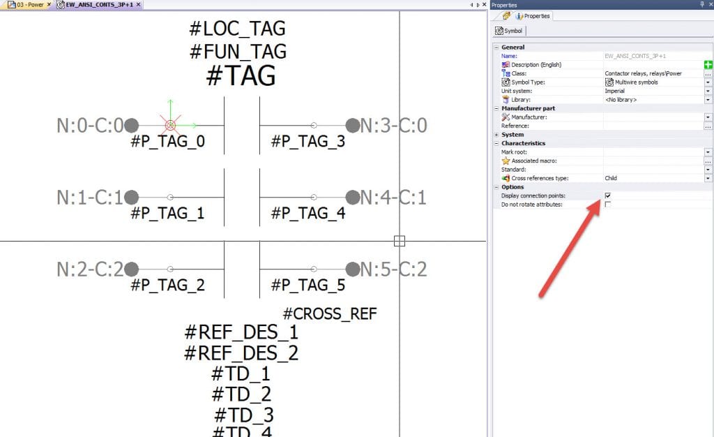
But, how do you know on the fly if the new symbol you’ve created had the proper grid spacing for its connection points? And, how do you know if you had your SNAPS turned on and set properly when you drew in your wires? We have a new way of doing just that by using something that was already there!
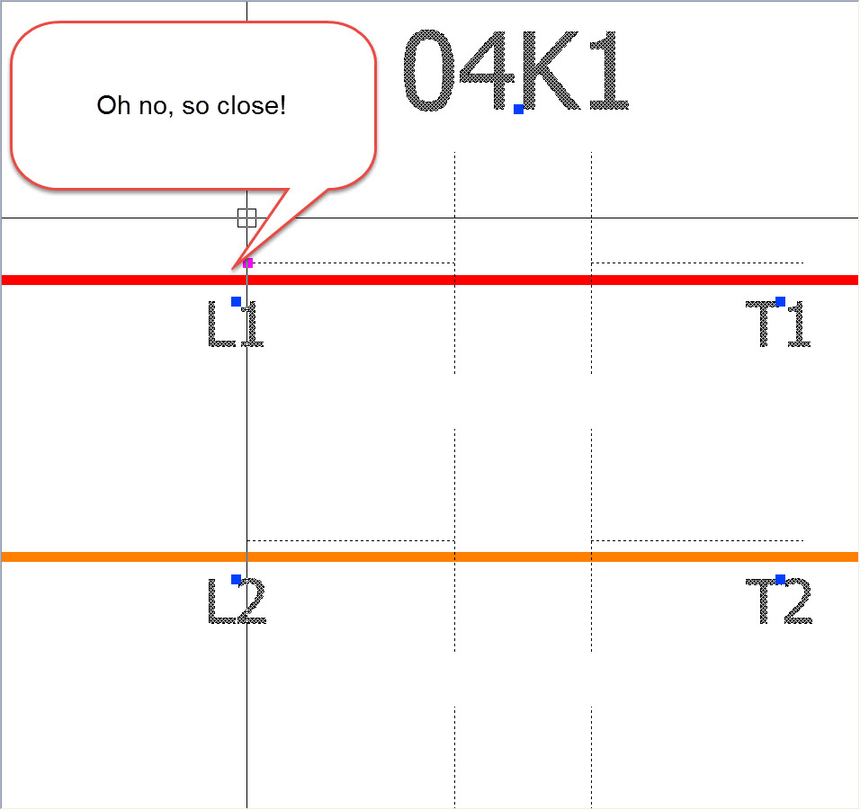
Connection dots were previously just a graphical indication of where a symbol’s connection points were lining up and could be shown or hidden based on the symbol settings. That all still applies. But now, on any symbol with Connection Dots enabled, an intelligent feature can show or hide depending on if a connection has been properly aligned. No more “close, but no cigar” or guesswork and rework!
Not to mention that getting close now actually DOES count to make a connection! New users will also appreciate that confidence boost in their initial designs and the new symbols that follow key spacing rules (.25 inches or 5 mm) for wires and connection dots.
So, make use of those new functions, and steer clear of missed connection regret.
Share
Meet the Author
view all posts by Evan Stanek
SOLIDWORKS Webinars & Power Hours
