Most designers and engineers associate simulation, analysis, and FEA with structural mechanics. Structural simulation tools are the most widely used type of simulation for understanding the stress, deflection and deformation, vibration, fatigue, and buckling responses for a part or assembly design under load. These tools can help health care and life sciences product developers answer important questions like: Will it break? Will it bend? Will it deform? Is it stiff enough? When will it wear out? Answers to these questions can help facilitate development, but many other types of integrated simulation tools can help these manufacturers accelerate time to market while improving quality and boosting innovation.
Structural Analysis
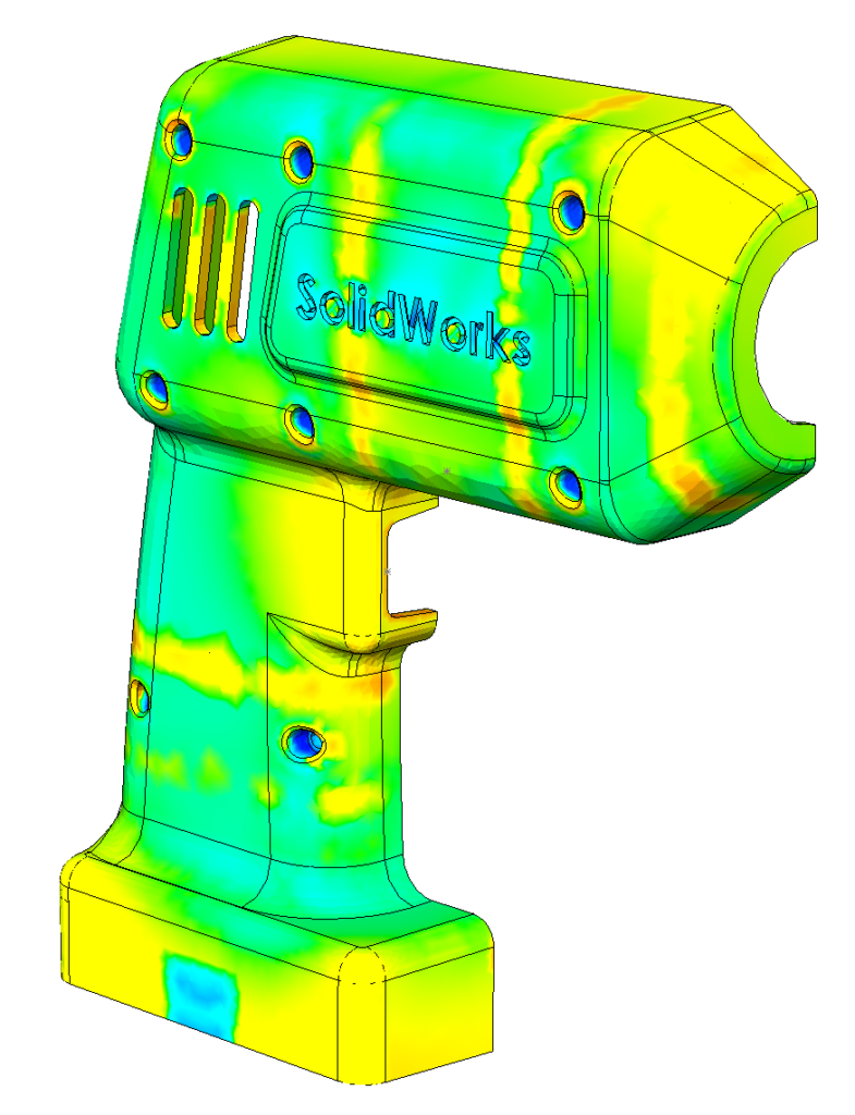
Healthcare and life sciences product developers need linear static stress analyses to locate high-stress areas that may cause component or assembly failure. By simulating the design’s structural response to operating conditions, engineers can reduce weight or material usage while maintaining performance, bring stresses within allowable levels, and verify the factor of safety.
In addition to linear static stress simulation capabilities, SOLIDWORKS provides simulation tools such as modal analysis for understanding the dynamic characteristics of components. This is another valuable simulation capability for designers because such studies calculate the natural frequencies and mode shapes of parts and assemblies. Dynamic behavior of a system can be determined using these results from Modal analysis.
SOLIDWORKS Simulation also has solutions for predicting how long a particular product will last based on usage. Extending a product’s lifespan—or ensuring that the product will continue to perform past its warranty period—requires an understanding of when the part will wear out. With SOLIDWORKS Simulation fatigue analysis tools, designers and engineers can predict the number of cycles or use over time before a specific component wears out and fail. With this valuable information, they can make design modifications to maintain or extend a part’s life.
Motion and Kinematics Analysis
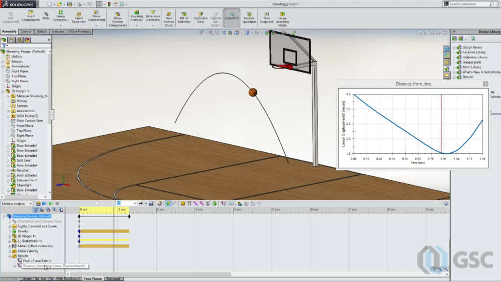
Although not all mechanical assemblies move, many assemblies, such as mechanisms, move a great deal. Using SOLIDWORKS kinematics and motion simulation tools, designers can see how their assemblies will move and analyze the effects of motion elements such as springs and dampers for the design, improving the accuracy of both assembly and individual component structural simulations. By simulating assembly movement, designers and engineers can better understand the entire assembly’s kinematics and quickly pinpoint areas that need improvement.
Learn best practices for SOLIDWORKS Motion Analysis >
Nonlinear Analysis
Although linear analysis tools can help solve many structural problems, other simulations—especially with complex products—require nonlinear analysis tools to obtain an accurate solution. Nonlinear structural analysis problems, distinguished from linear problems because the response is not proportional to the loads and boundary conditions, generally fall within three categories:
- Nonlinear materials
- Nonlinear geometries
- Nonlinear interactions between parts or structural nonlinearities
Most nonlinear problems involve all three types, as well as nonlinear loads/boundary conditions and nonlinear dynamics/vibration. Other nonlinear problems involve contact between parts or between the product and another object, such as drop tests. Nonlinear analysis tools are available in SOLIDWORKS Simulation Premium software and the cloud-based SIMULIAworks system.
Topology Optimization
Another type of integrated structural simulation that is particularly useful in helping designers and engineers develop innovative products is topology optimization. A topology study optimizes material distribution within a design space based on a set of loads, constraints, and goals to maximize the system’s performance. Typical goals include balancing the weight-to-stiffness ratio, minimizing mass, or minimizing maximum displacement—based on specific loads and geometric constraints, including those imposed by the manufacturing process used. Topology optimization is a valuable tool for generating innovative, organic design concepts, establishing starting points for the design team, or generating ideas for refining an existing design.
Thermal Analysis
In addition to simulating the impact of structural loads on a design, analysts need thermal simulation capabilities to understand how temperature and heat transfer effects influence structural performance. Such analyses provide the insights necessary for determining whether components of a system are overheated. If they are, engineers can use the same thermal analysis tools to validate that the heat transfer mechanisms remove enough heat to ensure optimal performance.
Understanding how heat transfer impacts design performance is important for an increasing number of products for safety and performance reasons. Many materials have temperature-dependent properties, and SOLIDWORKS analysis tools can simulate different types of heat transfer—including conduction, convection, or radiation—and calculate heat transfer within and between components in a design and its environment. These tools can simulate transient and steady-state effects. Thermal problems can be solved using either structural or fluid-flow analysis. In a thermal structural analysis, the effect of moving air or liquid becomes a load or boundary condition. In a fluid-flow analysis, the software calculates the thermal effects of moving fluids, whether the fluid is a liquid or a gas.
Multiphysics Analysis
While a large portion of simulation problems examine a particular type of physical phenomena—such as structural mechanics, structural dynamics, fluid dynamics, and thermal analyses—many situations require a combined multiphysics approach. Examples of multiphysics simulations include:
- Thermal stress or thermo-mechanical (thermal/structural)
- Fluid structural interaction (flow/structural)
- Fluid flow with heat transfer (flow/thermal)
- Fluid structural interaction with heat transfer (flow/thermal/structural)
The combination of SOLIDWORKS Simulation and SOLIDWORKS Flow Simulation provides a powerful, integrated suite for analyzing many possible combinations of physical phenomena, enabling designers and engineers to gain a definitive understanding of how various physical phenomena affect the way a design will function and perform.
Fluid Flow Analysis
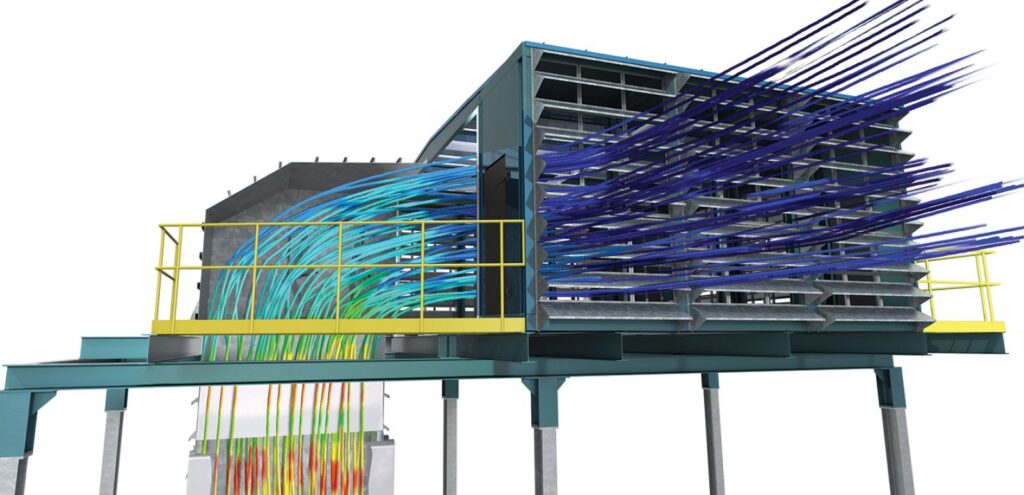
Product developers in the health care and life sciences market can use fluid-flow analysis, also known as computational fluid dynamics (CFD) analysis, to better understand how the behavior of fluids—either liquids or gases—affects design performance. Although initially used primarily as an alternative to expensive wind-tunnel testing for improving the aerodynamics of aircraft and automobiles, SOLIDWORKS Flow Simulation CFD analysis technology is now increasingly used to evaluate other flow-related issues, such as validating sufficient cooling of electronics in medical devices, ensuring adequate airflow in ventilators, maximizing the performance of microfluidics and laboratory equipment, optimizing the flow of molten plastics within molds, and refining other flow-based manufacturing and piping processes.
Learn how SOLIDWORKS Flow Simulation helped evaluate several design iterations of an Intubation Chamber and progressed its development for medical personnel here >
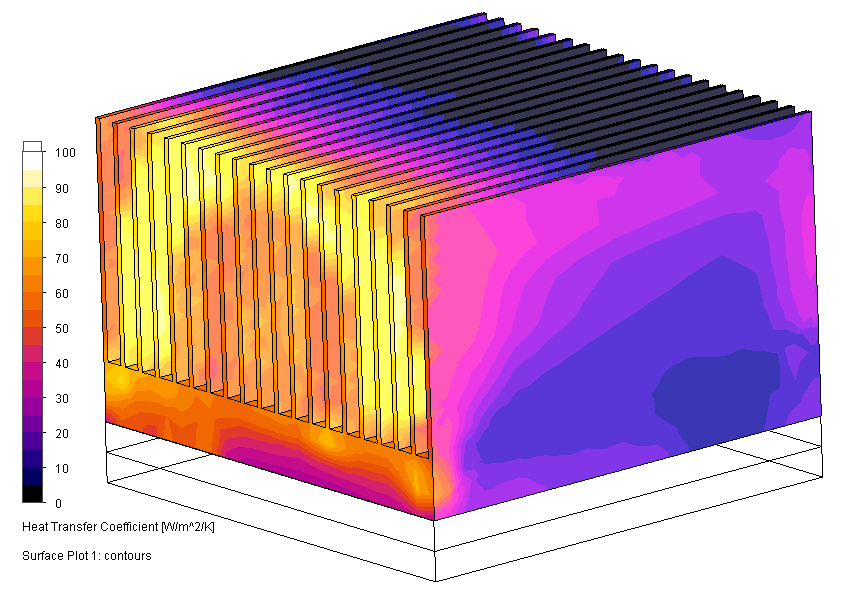
Electronics Cooling Analysis
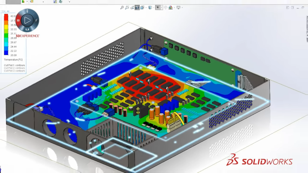
With the SOLIDWORKS Flow Simulation Electronics Cooling Module, designers and engineers are able to more easily optimize airflow and cooling in electronic systems, which are widely used in medical devices and monitoring and diagnostic systems. This powerful tool enables product developers to improve airflow and cooling, by moving components and/or creating air baffles and ducts; validate overall thermal performance by studying heat-up/cool-down cycles and maximum temperature under load; and pick the best heat sink, by assessing the impact of airflow cooling over the printed circuit board (PCB). Understanding and isolating the thermal characteristics of the PCB allows for evaluation of component placement and the use of heat pipes, thermal pads, and interface materials, as well as selection and placement of the ideal fan arrangement, which can have a dramatic impact on the overall thermal performance of a design.
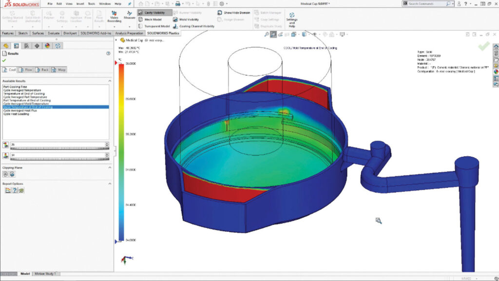
Plastics Injection-Molding Analysis
Plastics injection-molding analysis software allows product developers to simulate the injection-molding production process for plastic parts used widely in health care and life sciences products. This tool enables designers and engineers to evaluate the manufacturability of injection-molded parts during the early design stages. By simulating the mold injection process, product developers will understand how the mold will fill, whether there are any air traps or voids, and where parting and weld lines will be. With these tools, product developers can consistently deliver designs that don’t require manufacturing modifications, reducing the need to prototype tooling.
Contact Us
Have a question? We’re always available to talk over the phone at 262-790-1080, for you to leave a message or for you to submit a request – just contact us.
Share
Meet the Author
view all posts by GSC
SOLIDWORKS Webinars & Power Hours
