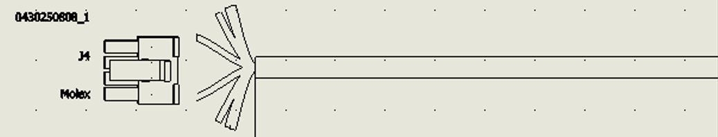
My story with connection labels began almost immediately after my introduction to SOLIDWORKS Electrical, and to be honest, it was love at first sight. The concept of a symbol that dynamically updated all my pin-by-pin wiring information and could go on ANY drawing type was life-changing. As wiring changes and connections took place, the label reflected those changes. This feature proved fantastic and light years ahead of typing out all that information in text boxes or spreadsheets! Beyond its primary function, I also discovered several other uses, some of which I go into greater detail here.
Custom Labels for Efficient Design
As I dug into creating my own custom labels, I realized that setting them up could be time-consuming, especially considering my current record being a 156-pin label containing 6 variables PER PIN. This first-hand experience turned into Enhancement Requests, some of which came to life quickly and greatly helped speed up the creation process. One notable improvement is the ability to “index” the attributes on a line, making it much easier to change the line-by-line info and reduce the time required to construct the labels.
Automating Label Creation
The ultimate request was for these labels to be drawn automatically instead of needing to build the library of symbols from scratch, similar to a PLC or Connector, which can be drawn on the fly by defining a configuration. Now that this functionality is in place, let’s look at reconfiguring and placing labels in drawings!
Configuring Label Appearance
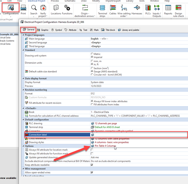
To customize a label appearance, we start in a familiar place, the Project>Configuration manager. In 2023 or newer, the Connection Label configuration option appears. The default options are solid, but you can adjust them to fill the label with exactly the content and format you prefer.
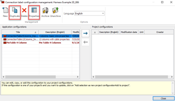
You can either edit one of the default examples or duplicate it to create and name your own. The options from here are straightforward. The Columns tab allows you to adjust, add, or remove key wire, terminal, and signal information.
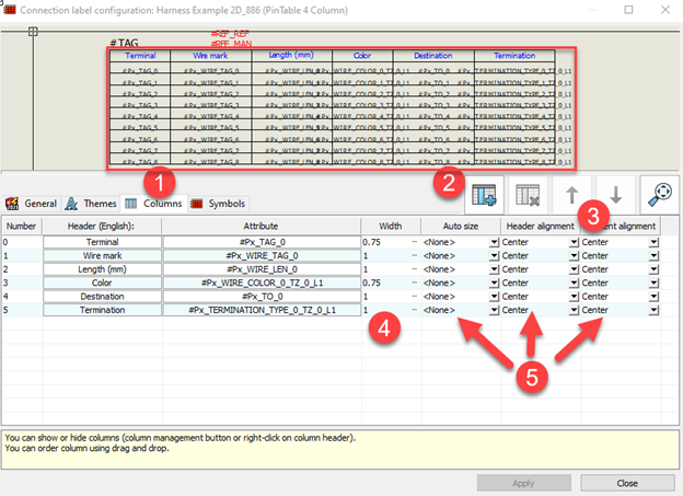
1) Columns tab displays your per-pin information attributes and previews the overall appearance
2) Choose to add or delete component terminal and wire information to your symbol
3) Re-order the columns with the up/down arrows
4) Change the width to appropriately size the column for expected content
5) Adjust the per-column text format
Shown here are the component’s Terminal text (pin 1, 2, 3 4), the mark, length, and color of the attached wire, the destination terminal where that wire lands, and the pin-by-pin termination type. Learn more about electrical terminations here.
Implementing the Dynamic Connection Label
Now that the format is settled, the preferred option can be set in the Project’s default configuration section. Otherwise, the configuration can be selected each time when using the Dynamic label tool.
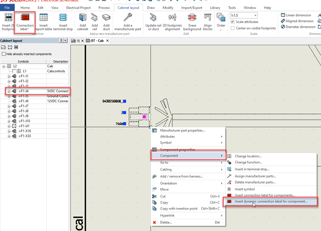
To test, place the label in a drawing, shown here is a 2D Layout drawing. To Add the “dynamic connection label,” users can either click the dedicated button, or right-click on a symbol, choose the “component” drop-down, and select there from the contextual menu.
This brings up the panel where the options can be selected to finalize the Connection Label’s information, appearance, and placement.
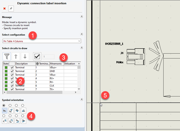
1) Select the configuration, the one chosen in “Project Configuration” default will show here automatically
2) Pick which circuits/terminals to display in the table
3) Add per-terminal information ON THE FLY (VERY NICE little feature to fill up your pin metadata)
4) Ensure proper orientation of the symbol
5) Position on the target drawing and click to finalize placement
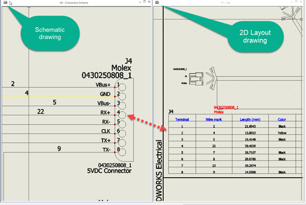
The newly placed label will automatically display the associated component’s pin/wire details, even as changes are applied. This ensures that component pinout details are always up to date for assemblers, troubleshooters, and other designers as wiring, part, and termination changes occur. Creating this condensed table of information would have taken a ton of time to create MANUALLY by hand of course, and a pain to keep up to date. But even the original symbol library approach would have taken some time. Now users can just let the “label maker” do the work!
Try it out; if connection labels are a common need in your drawings, this enhancement can save time, ease data entry, and cleanly display key information.
Join the SOLIDWORKS Community
This example also speaks to the constant efforts of developers to improve SOLIDWORKS Electrical! Most of the features implemented come from user experience, speaking to the effectiveness of the community in helping drive the direction and development of the program. My request became a reality, and your next idea can be brought to life as well! If you’ve ever wanted to add your own ideas to any of the SOLIDWORKS and 3DExperience tools, you can jump in and help direct the creation of the next great feature at www.solidworks.com/enhancements.
Share
Meet the Author
view all posts by Evan Stanek
SOLIDWORKS Webinars & Power Hours
