As a child of the ’80s, I’ll always remember the first time I saw MacGyver get out of a jam using the most elementary of tools he found in his surroundings (diffusing a bomb with a paperclip, please!). I’m sure his adventures were the inspiration for many careers in creative problem solving for profit (e.g., engineering). Our day-to-day work doesn’t quite have the same sizzle – drawing schematics just doesn’t have the same appeal for TV. However, SOLIDWORKS Electrical Connection Labels may just make you feel a little more like MacGyver, that is if he had access to the luxury of a Swiss Army knife instead of a wad of ABC gum and a paper clip.
Connection labels are completely customizable symbols that show a miniature “to/from” report for any component. The labels can appear as a simple table with rows and columns or as a display of the information with supporting graphics matching terminals and ins and outs to a real part footprint. Connection labels have the ability to call on information and display it in any part of your design (e.g., line diagrams, schematics, reports, 2D layouts, etc.), making it a pretty versatile tool. Hence, the Swiss Army knife comparison!
Once you’ve populated the rest of your library and have thoroughly defined your schematics, you can then get to the fun part of retrieving “the good stuff.” Just like reports, connection labels are perfect for retrieving the information you’ve already built into your parts and design.
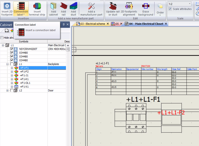
There are two types of labels, blue and red. Blue represents the circuit information (to/from, wire/cable info, terminals) of a manufacturer part in your design.
These can be directly mapped as a default within the manufacturer parts properties!
The red connection labels represent detailed information based on the top level component in your design (multiple parts apply!).
There is a host of attributes available for display, and the label will instantly update the information for which they point to reflect changes in other parts of the design. Some labels are packaged by default in SOLIDWORKS Electrical, but you can also take a crack at customizing options to fit your needs.
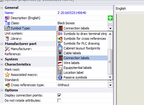
You can always create a new label just as you would for any other symbol (be sure to select “Connection Label” in the symbol type drop-down). Or, make a copy of an existing label and save time using the copied attributes instead of clicking to insert your own.
Of course, we can display the usual information (e.g., component mark, manufacturer, descriptions, reference number), but further down in “Connection Point” is where the REALLY good stuff lives.
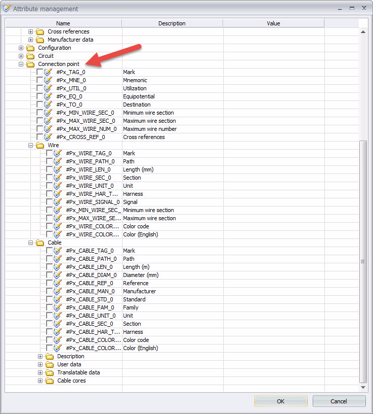
From terminal mark and mnemonic information to wire and cable assignments to wire cross sections to cable cores and properties and much more, all are at the ready and can be called upon using the corresponding attributes. When selecting your attributes, SOLIDWORKS Electrical will ask you which circuit you want to use for the labels and will apply the proper circuit tag accordingly!
Since the majority of the symbol work for connection labels deals with attributes, here are a few helpful tips to make connection labels more efficiently.
- Make your largest connection label first (most terminals needed), then copy/paste the attributes you’ve chosen for all other smaller labels to avoid re-inserting/renumbering.
- Use of left > right vs. right > left dragging to select only the parts of your symbol that you’re working on.
- If a table or generic symbol is sufficient, reuse the same connection label for many types of components to get the point-to-point information you want.
- Make use of “copy properties” and “apply copied properties” to make all your attributes match in style, justification, and size.
- Remember, you won’t need to add connection points, those are only needed for multi-wire symbols!
- Use the “array” and “multiple copy” commands to quickly and evenly place lines and text when placing grid lines or copying attributes.
Don’t hesitate to try it out and experiment to see how it fits into your engineering process.
Share
Meet the Author
view all posts by Evan Stanek
SOLIDWORKS Webinars & Power Hours
