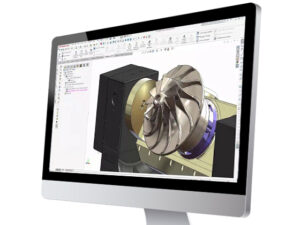
SOLIDWORKS motion analysis, included with SOLIDWORKS Simulation Professional and Premium, uses the assembly mates along with part contacts and a robust physics-based solver to accurately determine the physical movements of an assembly under load. But, how do you know if you’re making the most out of this powerful tool?
A client in the stamping industry recently asked me this question, so I’ve compiled a list of best practices for performing motion analysis studies. While this compilation is handy for any business using SOLIDWORKS Motion in their manufacturing processes, these best practices are not a replacement for proper training for this tool. If you’re seeking a deeper understanding of how to use SOLIDWORKS Motion, consider attending one of our upcoming classes.
As a general rule, it’s important to make sure the time bar in your motion simulation is set at zero before making any changes. It’ll save you time and frustration. Now, on to the best practices!
Best Practices for SOLIDWORKS Motion Analysis
When dealing with assemblies
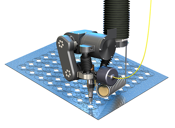
Group all components that “move together” into subassemblies. Subassemblies in SOLIDWORKS Motion are assumed to move rigidly and the mates within the subassembly don’t make a difference. This will make managing the mates in your motion study a lot easier.
Create a template for each typical setup, allowing interchangeable parts to be replaced and updated. If you have a setup used for fine blanking, create an assembly that contains only the most necessary components, primarily the ones that move.
Things like bolts that simply affix an assembly in place are usually not necessary unless that whole portion of the assembly also moves, and the mass of those bolts is critical in the mass calculation of the assembly.
This template is a SOLIDWORKS Assembly file that can be copied for each new job. The items that change, such as dies and specific tools, can be changed out as necessary. The reason for using this template is because things like contacts only need to be set up once. Check, double-check, and triple-check, then when someone else uses it they only need to worry about a few specific changes instead of a very complex setup of a full machine.
When creating motors
If you have specific motor timings, SOLIDWORKS Motion allows you to define these as expressions, or time vs. distance, velocity, acceleration. The options are endless.
Typically, companies have a few different timings and these can be saved as .sldfnc files to be pulled up by engineers as needed. The key item here is staying organized. Putting the file in a network folder and making sure everyone has read access, but not write or editing permissions. Someone should administer the network folder and update with new timings on request from other engineers. That way, the company naming schemes can be followed ensuring someone can’t accidentally change the timings.
If the network folder houses many files, it may be a good idea to create a backup in case there is any chance for future corruption.
In this template assembly file, it is best to pre-define the critical results you would like most engineers to look at. That way it won’t waste their time having to define the plots of interest many times over when running similar analyses.
When creating springs and dampers
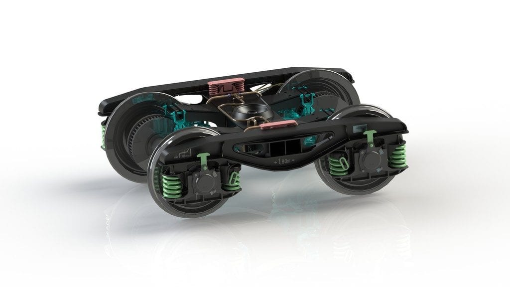
It’s easy to create springs and dampers in SOLIDWORKS Motion. However, it can sometimes be cumbersome to gather the manufacturer information and/or testing depending on the accuracy of data you desire.
If you use a handful of springs repeatedly and you want to test them and/or include their damping components, it may be worth creating a library with the properties you’ve determined. That way, your engineers won’t need to look up the properties each time.
To do this, create a spring (or damper) with the properties you want to save. Then, find it in the motion tree, right-click, and choose to add it to the design library. At this point, it will ask you to name it and save it to a specific folder. Again, I’d recommend a location that is both on the network, has appropriate read/write permissions to protect against accidental overwriting and assign an administrator. It will likely be the same person administering the motor functions folder.
When creating forces
In SOLIDWORKS Motion Simulation, forces usually represent some sort of resistance that isn’t modeled in the CAD Model. It can be used to represent friction that isn’t captured through a contact, or it can represent a material that isn’t easy to model, or it can be used as a motor that is based on force values rather than actual movement. In the same fashion as springs, a library can be set up and created. The difficulty here is that forces usually represent more unique items and are less likely to be standardized. However, if you feel there is something that would be used repeatedly that is not easily captured by the other items in Motion Simulation, a library of forces can be created as well.
- Whether to include gravity or not:
Every analysis can include or exclude gravity, choosing to include gravity depends on the impact on your analysis. If the weight of the parts is low in comparison to the forces (e.g., 1 lb. weight vs. 100,000 lb. press), then it is likely negligible. However, it’s important to think through the entire analysis. Is there any point where the large forces stop and gravity takes over? Even if gravity takes over for just a moment, then it’s likely gravity needs to be included. The reason it’s recommended to leave it off, if possible, is it increases the calculation time of an analysis. - Choosing the appropriate frame rate and integration step size
Both items should be set based on the speed at which things are moving within your analysis. Typically, the threshold is 32 frames per second for human perception of smooth motion. If you have something that runs in a cycle time of 0.01s, you’ll want to create an animation to slow that down and play it over 5 seconds in a smooth looking fashion. You would need a minimum of 160 (32 frames per second * 5 seconds) frames. By taking that number of frames and dividing by the physical time it would yield 16,000 (160 frames/0.01s) frames per second. Those are the setting you need SOLIDWORKS Motion to create a nice animation.
The frame rate is based on how often SOLIDWORKS writes the image moving, not how often a calculation takes place. The calculations should take place much more often to get accurate results. In most cases, if something is moving through a range or cycling, you will want at least 10 and most likely 100 calculations between frames. This is where you can set the maximum integrator step size. Minimum integrator step size is up to you and depends entirely on your desired wait time and accuracy for the analysis.
Looking for a printer-friendly version of this blog for your files? Download it here.
Share
Meet the Author

